

Writing use cases is the most important step for modeling user requirements. Use cases focus on describing scenarios of using the system and are usually written in a textual form. To assist use case writing, various templates have been proposed, mainly differing in their visual representation. XML is a platform independent language for describing data and their structure without referring to their visual presentation. Here, we will propose the writing of use cases in XML. Using XML, we achieve the clear separation of the semantic part of use case descriptions from their visual representations. Hence, the same description can be visualized in many different ways. Furthermore, our encoding allows the integration of tools for Writing and validating use cases. We introduce an appropriate structure for use case descriptions and we model this structure using DTD (Document Type Definition).
Use cases constitute the basic way of modelling user requirements during software development. Nevertheless, there exist no standard rules for writing them. During the last years, many templates have been proposed for writing use cases. Some examples are the fully-dressed, the table, and the two-column format. Essentially, all these formats contain the same information presented in a different way. Also, different levels of detail are needed in different phases of software development. This need presupposes that the information is not degraded during its transformation in more detailed forms. XML (eXtensible Markup Language)is a language for data description, which has the potential of representing information in different forms, as well as, in different levels of detail. Compared to other documents, such as HTML and PDF, an XML document is not bound to an explicit output format. With the description written in XML, it is possible to produce any of the desired formats without rewriting the contents.
Our aim is to define a technique that will assist developers in writing use cases, without bothering about its visual representation, while at the same time respecting the logical structure of a use case. For visualization purposes, we provide several XSLT transformations that can be applied and result different visual formats in different levels of detail.
Use Cases:
Use cases are a technique for documenting functional requirements of a system under development. User requirements are modeled twofold: writing use cases descriptions and constructing a use case diagram. A use case diagram is composed of use cases and represents the global system’s behavior. Each use case corresponds to an exact behavior of the system that satisfies a user goal. Formally, a use case is defined as a sequence of events that illustrates the behavior of a system and its components when a service is invoked this behavior is described in several ways but the most common one is the textual description.
Although use case diagrams and use cases are practical, they have important semantic weaknesses in their notation. The use case description is usually written in simple text. There are no official guidelines for writing use cases, several techniques and practices were describe use case scenarios. We will distinguish three basic presentation forms of use cases:
- Natural Language Text: Simple textual description is the easiest and the most popular way for specifying a use case. This is an informal specification and thus includes many ambiguities. In a high level of analysis, the textual description is useful because it gives freedom of expression.
- Tabular Representations: This presentation is based on structured and sequential Textual description. The progression of rows in the table encodes the flow of the events. Events are numbered and each scenario is described as a unique sequence of events. In a two-column representation, entries in the first column correspond to the actors’ interactions, while entries in the second column are descriptions of the system actions. In a single column vertical sequence, a total ordering of the events is represented by the rows.
- Directed Graphs: Graphs are used for the simultaneous representation of all the scenarios of a use case. A node corresponds to a state of the system and an arc to a transition fired by an event.
Use cases are central artifacts in many phases of the software development cycle. During the requirement analysis, they are useful to specify requirements. At the design phase, they drive the creation of interaction diagrams. During the testing of the system, they are used for deriving test cases. The utilization of use cases in different phases of the software life cycle implies different levels of precision. Simple textual descriptions are sufficient during the analysis.
Since no information concerning the internal behavior of the system is known. In the design phase, more detailed information is presented with tabular representations in which the flow of events is clearly shown. Directed graphs, on the other hand, can help to the creation of the corresponding test cases. Consequently, a single presentation of a use case is not sufficient.
During development, several representations of the same use case, constructed increment ally, should be maintained. Furthermore, a use case refinement should not change the behavior given in the main description. Thus, a technique is required for the structured description of use cases, which allows the incremental addition of detail, by preserving the properties of the original. The technique should allow multiple representations of the same use case, via transformations. As we demonstrate in this paper, our approach achieves these objectives.
XML:
XML is an extensible mark-up language that was published as a W3C recommendation in 1998. Some of the objectives for the design of XML were the easy usage over the Internet, the legibility of the documents, and the minimality of the language. XML supports a wide variety of applications such as logical data description (databases, documents) and conceptual data description. Extensibility is a key feature of XML. Authors can declare and use their own tags and attributes. XML offers a convenient syntax for data representation providing little semantic information. Thus, XML emphasizes on the description of the content separately from its presentation.
Although an XML description already implies a logical data
structure, in order to validate this structure, syntax rules may be provided
explicitly. XML offers the possibility of creating document type definitions
(DTD) that define constraints on the logical structure of XML documents. A DTD
defines a grammar of element types and attributes for each element. An XML
document that conforms to an associated DTD structure is called “valid”.
XML does not deal with presentation issues; presentation is
addressed by XSLT (XML Style Language Transformations). XSLT is a rule-based
declarative language, which is used for writing transformations. An XSLT
transformation parses a valid and well-formed XML document and transforms it
into another document. The transformation might range from a simple
visualization of the contained data (e.g. in HTML), to a complex processing or
restructuring of the data for any desired purpose. XSLT was designed for use as
part of XSL (extensible style sheet language for XML). XSL also includes an XML
vocabulary for specifying formatting. XSLT is used to describe how the document
is transformed into another XML document that uses the formatting vocabulary.
Nevertheless, XSLT was also designed to be used independently of XSL, as we do
in this article. The transformations that we produce are mainly to HTML
documents for previewing
Modeling Use Cases in XML:
To model use cases in XML, we have to define the logical structure that the description should follow. By analyzing the concepts related to use cases, we construct a logical meta-model of use cases and present this using a UML class diagam. Then we transform the class diagam into a document type definition (DTD) for XML documents. This DTD file presents the structure and the validity constraints of XML documents modeling use cases. Using the DTD one may write use cases in XML and validate them. Although the descriptions written in XML are fairly legible, the presence of tags may confuse readers. Therefore, we de?ne XSLT transformations that present use case descriptions in several common formats.
Modeling the Use Case Structure in UML:
In this section, a standard structure for use cases is presented. This structure is semiformal and contains the most important information for describing use cases. We provide a UML class diagram pic_1 to illustrate the structure. The functional requirements of a system are described as a set of use cases (use case set). The use case set is defined as a composition of all actors (users of the system) and use cases (the distinct functionalities that the system provides to its users).

A use case may consist of several scenarios. One of them is the main scenario and the rest are called alternative scenarios. A scenario describes a flow of events. One of the actors causes the first event that activates the use case. The rest of the events are caused by a system component or by an actor, when the system needs more information to go on. The main scenario describes the most usual flow of actor-system interactions. It corresponds to the case in which no problems occur. The alternative scenarios describe the behavior of the system when exceptional events happen. Alternative scenarios are usually modeled by extensions. An extension is a sequence of extra steps that is activated when a condition is satisfied (the condition corresponds to the occurrence of an exceptional event).
In the depicted class diagram, a use case is defined as a composition of exactly one main scenario and any number of extensions. Further, both the main scenario and the extensions are composed by several steps that are distinguished by a unique number and they are activated by the actor or from the system itself (role name who of the association). An extension is activated when a condition is satisfied and refers to an exact step (role name extending of the association) of the main scenario. UML defines three types of relationships between use cases: “include”, “extend”, and “generalize”. The most frequently used is the “include” relationship. Parts of scenarios that are repeated in many use cases are usually described separately and then included in any step of a use case by simply referring to the included use case.
The “extend” relationship is not used so frequently. In cases in which extensions are too lengthy or complicated, it is advised to model them as separate use cases on their own. The extension use case then is said to extend the main use case at a specific step under some condition. Finally, the generalization relationship is used rarely; we do not deal with this relationship in our modeling. The “include” relationship is defined as a role name of a use case associated with a step. Any step may include a use case; it is common practice to include the same use case in many steps in different use cases (this is the usefulness of “include”). The “extend” relationship is defined as a role name of the use case that extends the main use case. The attribute extendStep defines the step of the main use case that is being extended.
By translating the class diagram presented, we create a DTD description (pic_2_). Each of the classes corresponds to an entry element. The composition relationship is modeled as a containment relationship; for instance, the element UseCaseSet Contains as children ( at least one) actor and (at least one) usecase elements. Role names are modeled as attributes in the attribute list of the elements; for instance, extends is defined as an optional attribute of element usecase.
The validity constraints in the DTD guarantee a simple kind if referential integrity of the XML document contents. Values of type ID cannot appear more than once in an XML document as a value of this type. This guarantee, for instance, that all use cases carry unique names; the same holds for actors. IDREF values must match the value of some ID attribute. For instance, an included use case name in a step(includes attribute of element step) must already exist as the name of one of the use cases.
XSLT Transformations:
Here, we describe some of the possible XSLT transformations that could be of value for developers. We separate transformations in four categories:
In the depicted class diagram, a use case is defined as a composition of exactly one main scenario and any number of extensions. Further, both the main scenario and the extensions are composed by several steps that are distinguished by a unique number and they are activated by the actor or from the system itself (role name who of the association). An extension is activated when a condition is satisfied and refers to an exact step (role name extending of the association) of the main scenario. UML defines three types of relationships between use cases: “include”, “extend”, and “generalize”. The most frequently used is the “include” relationship. Parts of scenarios that are repeated in many use cases are usually described separately and then included in any step of a use case by simply referring to the included use case.
The “extend” relationship is not used so frequently. In cases in which extensions are too lengthy or complicated, it is advised to model them as separate use cases on their own. The extension use case then is said to extend the main use case at a specific step under some condition. Finally, the generalization relationship is used rarely; we do not deal with this relationship in our modeling. The “include” relationship is defined as a role name of a use case associated with a step. Any step may include a use case; it is common practice to include the same use case in many steps in different use cases (this is the usefulness of “include”). The “extend” relationship is defined as a role name of the use case that extends the main use case. The attribute extendStep defines the step of the main use case that is being extended.
Modeling the Use Case Structure in a DTD Description:
The validity constraints in the DTD guarantee a simple kind if referential integrity of the XML document contents. Values of type ID cannot appear more than once in an XML document as a value of this type. This guarantee, for instance, that all use cases carry unique names; the same holds for actors. IDREF values must match the value of some ID attribute. For instance, an included use case name in a step(includes attribute of element step) must already exist as the name of one of the use cases.
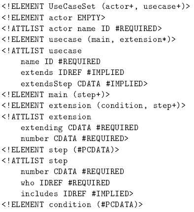 |
| pic_2 : Document Type Definition (DTD) for the use cases. |
XSLT Transformations:
Here, we describe some of the possible XSLT transformations that could be of value for developers. We separate transformations in four categories:
- visualization:An XML document can be transformed into and viewed as an HTML file (or any other output form such as PDF, TEX, and RTF) using the appropriate XSLT transformation. Most important than that, the format of the use case can be in any of the common template formats, such as the simple text, one-column, and two-column format. This solves the problem of choosing the appropriate format before writing the use cases. Decisions to change the representations do not affect the written use cases, since they are written independently of any visualization. In particular, the transformation into HTML allows the automatic integration of hyperlinks in the document. This results in a hypertext software documentation, which is easily accessible, navigable, and distributable in an enterprises network.
- validation:
Validation The validation of an XML document against its associated DTD already provides a means of checking use cases for consistency. The validity constraints of the DTD guarantee that: (a) all actors initiating use case steps are specified beforehand as members of the use case set; (b) included and extended use cases refer only to existing use cases. Apart from these checks, we may define XSLT transformations that perform more complex tasks.
- metrics:
Metrics Interesting measurements can be easily derived by suitable XSLT transformations such as the number of use cases and actors, and the average number of steps or extensions. When regularly collected, these measurements can be used for the assessment of the quality, the estimation of the complexity of the project, and further project estimation purposes.
- tools integration:
Tools integration One of the objectives of XML is the easy exchange of information between many applications. Transformations may be written that transform the use case documents into formats readable by existing CASE tools. Apart from that, the collections of all XSLT transformations (for visualization, validation, metrics, etc.) can play the role of an open and extensible repository of tools for requirements engineering. An application providing a graphical use interface for writing the XML files and offering all transformations will be of a great value to developers.
[Dimitris Dranidis, Kalliopi Tigka]
[Computer Science Department, City Liberal Studies]
[Computer Science Department, City Liberal Studies]


No comments:
Post a Comment